This page describes the results of the performance analysis of three VST plugins, performing Ambisonics decoding of 2nd-order horizontal-only surround sound recordings.
The signals contained in a second-order B-format stream (or WAV file) are:
W - omnidirectional, scaled by -3 dB: 0.707*signal
X - forward-pointing figure of 8: cos(θ)*signal
Y- left-pointing figure of 8: sin(θ)*signal
U - forward-pointing four-leaf: cos(2*θ)*signal
V - front-left pointing four-leaf: sin(2*θ)*signal
In which θ is the azimuth angle measured conterclockwise starting from front.
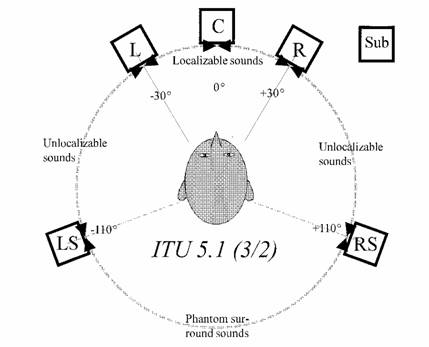
The decoders are fed with this 5-channels stream, and produce as output another 5-channels stream, formatted according to the ITU 5.1 geometry:
The order of the channels, as saved in a 6-channel Wave-Ex file, is the following:
FL - FR - C - LFE - LS - RS
Of course, the LFE channel is silent
Three decoders have been tested:
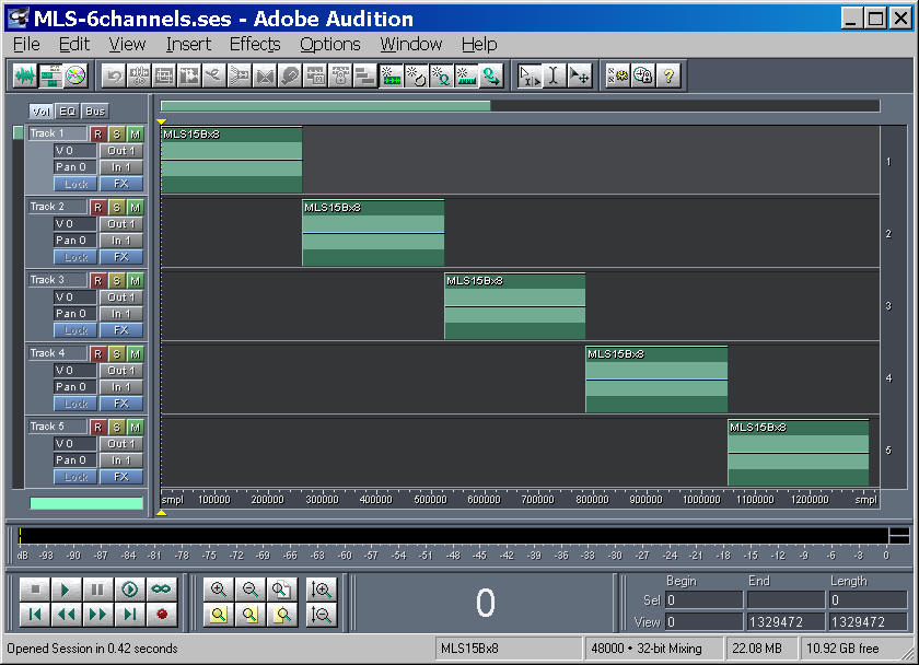
The tests have been performed employing AudioMulch, feeding the decoder with a MLS signal which is sent separately to each of the 5 inputs, and recording the 5 outputs in a standard 6-channel Wave-Ex file.
The following pictures show AudioMulch as it was set up for the test with each decoder:
Finally, the next picture shows the multichannel test signal employed (MLS signal repeated on each channel):
Analyzing the signals being output from each decoder, it was possible to compute the gains employed by each decoder in the matrixing process.
Generally speaking, each of the 5 loudspeaker feeds can be computed as a weighted sum of the 5 inputs:
Feed = G1*W + G2*X + G3*Y + G4*U + G5*V
Therefore, it is possible to compile a table, containing the values of these 5 gains for each of the output channels (loudspeaker feeds).
The gain of the system was calibrated, for all decoders, in such a way that a signal coming frontally to the listener has unit gain over the Center loudspeaker.
Here are the results for the three decoders:
| Gerzonic Emigrator "halfway between strict soundfield and controlled opposites" | |||||||
| Name | Angle | Coordinates | W | X | Y | U | V |
| L | 30 ° | 0.8660,0.5000,0.0000 | 0.0000 | 1.3661 | 0.3660 | -1.3661 | 0.3660 |
| R | -30° | 0.8660,-0.5000,0.0000 | 0.0000 | 1.3661 | -0.3660 | -1.3661 | -0.3660 |
| C | 0° | 1.0000,0.0000,0.0000 | 0.4714 | -1.8215 | 0.0000 | 2.4882 | 0.0000 |
| LS | 120° | -0.5000,0.8660,0.0000 | 0.4714 | -0.4553 | 0.3660 | 0.1220 | -0.2113 |
| RS | -120° | -0.5000,-0.8660,0.0000 | 0.4714 | -0.4553 | -0.3660 | 0.1220 | 0.2113 |
| Gerzonic Decopro "weights 0.707 0.571 0.514" |
|||||||
| Name | Angle | Coordinates | W | X | Y | U | V |
| L | 30 ° | 0.8660,0.5000,0.0000 | 0.4458 | 0.3121 | 0.1802 | 0.1621 | 0.2809 |
| R | -30° | 0.8660,-0.5000,0.0000 | 0.4458 | 0.3121 | -0.1802 | 0.1621 | -0.2809 |
| C | 0° | 1.0000,0.0000,0.0000 | 0.4458 | 0.3603 | 0.0000 | 0.3243 | 0.0000 |
| LS | 110° | -0.3420,0.9397,0.0000 | 0.4458 | -0.1232 | 0.3386 | -0.2485 | -0.2084 |
| RS | -110° | -0.3420-,0.9397,0.0000 | 0.4458 | -0.1232 | -0.3386 | -0.2485 | 0.2084 |
| Bruce Wiggins WIGWARE "ITU cardioid" |
|||||||
| Name | Angle | Coordinates | W | X | Y | U | V |
| L | 30 ° | 0.8660,0.5000,0.0000 | 0.4724 | 0.7143 | 0.7258 | 0.0000 | 0.3456 |
| R | -30° | 0.8660,-0.5000,0.0000 | 0.4724 | 0.7143 | -0.7258 | 0.0000 | -0.3456 |
| C | 0° | 1.0000,0.0000,0.0000 | 0.3226 | 0.7719 | 0.0000 | 0.0000 | 0.4724 |
| LS | 110° | -0.3420,0.9397,0.0000 | 0.9101 | -0.7834 | 0.9562 | -0.0806 | 0.0000 |
| RS | -110° | -0.3420-,0.9397,0.0000 | 0.9101 | -0.7834 | -0.9562 | -0.0806 | 0.0000 |
It must be noted that all the three decoders had some variable settings, which were left at their default position. However, it was verified that with Emigrator even moving the slider at extreme positions (strict soundfield or controlled opposites) did not change the decoding matrix at all.
The coefficients obtained by Gerzonic Emigrator are exactly those published by Richard Furse on http://www.muse.demon.co.uk/ref/speakers.html
It must be noticed that these Furse coefficients are completely wrong, as it will be shown thereafter.
The Decopro coefficients are "classical", in the sense that they synthesize simmetric, constant-directvity virtual microphones for all of the 5 output channels.
The Wigware decoding coefficients are, theoretically, of the "advanced" type, which means that different directivities are synthesized for the virtual microphones feeding the C, L&R and LS&RS loudspeakers, providing smoother coverage of the whole circle despite the uneven angular spacing of the ITU layout.
A first way to assess the behaviour of the three decoders is to compute the 5 speaker feeds for 5 special test signals, representing a single sound source located exactly at the same angle as each of 5 loudspeakers. That is, at +/- 30° at 0° and at +/- 110°. In reality, the Emigrator (Furse) coefficients are derived theoretically for the case in which LS&RS are located at +/-120° , and consequently the verification will be done for these angles, for this decoder.
It is possible this way to create a matrix presenting the gain of the speaker feeds for the 5 positions of the virtual source, as shown here:
| Emigrator | Source position | ||||
| Speaker signal | Left | Right | Center | Surround Left | Surround Right |
| L | 1.000 | 0.000 | 0.000 | 0.000 | 0.000 |
| R | 0.000 | 1.000 | 0.000 | 0.000 | 0.000 |
| C | 0.000 | 0.000 | 1.000 | 0.000 | 0.000 |
| LS | 0.000 | 0.000 | 0.000 | 1.000 | 0.000 |
| RS | 0.000 | 0.000 | 0.000 | 0.000 | 1.000 |
| Decopro | Source position | ||||
| Speaker signal | Left | Right | Center | Surround Left | Surround Right |
| L | 1.000 | 0.333 | 0.789 | 0.073 | 0.095 |
| R | 0.333 | 1.000 | 0.789 | 0.095 | 0.073 |
| C | 0.789 | 0.789 | 1.000 | -0.056 | -0.056 |
| LS | 0.073 | 0.095 | -0.056 | 1.000 | 0.096 |
| RS | 0.095 | 0.073 | -0.056 | 0.096 | 1.000 |
| Wigware | Source position | ||||
| Speaker signal | Left | Right | Center | Surround Left | Surround Right |
| L | 1.302 | 0.342 | 0.903 | 0.422 | -0.236 |
| R | 0.342 | 1.302 | 0.903 | -0.236 | 0.422 |
| C | 0.764 | 0.764 | 1.000 | -0.278 | -0.278 |
| LS | 0.308 | -0.422 | -0.175 | 1.460 | 0.089 |
| RS | -0.422 | 0.308 | -0.175 | 0.089 | 1.460 |
It can be seen how the Emigrator/Furse matrix is theoretically perfect: when the sound is coming form the direction of one given loudspeaker, the signal is being output only by that loudspeaker, and all the others are muted. However, this only works for these 5 selected directions: if the sound is coming from any other direction, it will be completeyly messed up, appearing from the wrong loudspeakers and with wrong polarity.
In fact, if we compute the polar plot of the directivity pattern of the virtual microphone associated which each speaker feeds, we get these three figures for Emigrator:
Of course, the Right and Right Surround patterns are simply simmetrical to those of Left and Left Surround, respectively, so there is no need to show them here.
We notice that these polar plots provide the prescribed unit gain for the case of the source angle equating the loudspeaker angle, and the zeroes for the other 4 "standard" directions, but the values go crazy for any other angle.
Much better results, instead, are provided by Decopro, as shown in the following 3 pictures:
In this case we see that the polar pattern (some sort of 2nd-order hypercardioid) is kept constant, and the aiming of the virtual microphone is exactly the same as the angle of the corresponding loudspeaker.
Albeit this decoding approach is sensible and works reasonably well, this is still under-optimized.
Bruce Wiggins did show in his Ph.D. thesis how to optimize the coefficients of the deocoding matrix, obtaining better uniformity of reproduction all around the circle, and minimizing the angular error between the encoded signal and the signal being reconstructed by the loudspeaker array. Such optimized coefficients are found in his Wigware decoder, and the corresponding polar patterns are shown here.
It can be seen that these "optimized" coeffients yield directivity patterns which are different for C, L&R and LS&RS: C is more directive, L&R a bit less, and LS&RS much broader (as they have to "cover" a wider angle). Also the aiming angles do not correspond to those of loudspeakers: whilst C is, obviously, centered, L&R are aimed at approximately +/- 45°, and LS&RS are aimed at approximately +/- 125°. These are not "errors", it is the way that these "optimized" coefficients works, attempting to minimize the reproduction error inherent in an irregular loudspeaker array.
CONCLUSION
The conclusion is:
- Emigrator employs the Furse coefficients, which are plainly wrong.
- Decopro works reasonably, but features constant-directivity virtual microphones, with aimings perfectly corresponding to the speaker angles, and this is suboptimal in the case of a strongly-irregular loudspeaker array.
- Wigware is the best one, providing spatially-optimized variable-directivity patterns, which should provide better reproduction and more uniform surround sound.
Of course, what above should be checked by blind listening tests, which I have plan to do in the following weeks.
The Excel file containing all the data obtained by these experiments can be downloaded here.
People wanting to replicate the experiments can find the Audiomulch configuration files and the multichannel test signal here.
More information on "advanced" decoders for irregular arrays can be found in the Gerzon/Barton AES paper at the Vienna convention (1992) and the related US patent. Both can be downloaded here.
(C) Angelo Farina, 6 November 2006